On Thursday, March 8th, the North Richland Hills MakerSpot is hosting its first ever Community Build, producing E-nable prosthetic hands for kids in need. This is awesome.
Read MoreScaling
No, I'm not talking about dermatology here. I'm not that kind of doctor.* Last week in a blog about modularization of 3D printing I promised to return with more detail about that project. This is one of those installments. We're going to talk about one of my favorite aspects of OpenSCAD, the ability to use variables in 3D modeling.
This is a particularly interesting topic to me because variables probably seem second nature to those familiar with programming in other contexts, but they're not a fundamental concept to many 3D modelers, particularly those who use sculpting tools rather than scripting. It's like English versus Russian. Both tools serve the purpose of communication but a fundamental element of English, the article, doesn't even exist in Russian. That's why Boris and Natasha are always looking for moose and squirrel rather than THE moose and A squirrel.
In this example I'm going to create the box bottom used for my dice/pawn box. The catch is, I need different sizes of this box -- my Film Tycoons pawns are much taller than standard dice, so a box for the former must be taller than the latter. Also, I may want to change the width of the box to accommodate more than six dice or pawns, right? If I were doing this in a standard drag and drop visual editor I'd end up making multiple copies with slightly different sizes. Very inefficient.
Incidentally, if you develop an impromptu love of OpenSCAD and you're in the Dallas/Fort Worth area, I'm teaching an introductory course March 8th at the Maker Spot.**
Let's walk through some code! This is an example, not a tutorial, so I'm going dive into it rather than building up from scratch. If you're new to scripting I wouldn't expect you to learn the language from this. Rather, if you're interested in 3D modeling I hope this'll inspire you to consider learning OpenSCAD to pursue it.

Like many programming languages I'm going to start out defining a bunch of variables. Ignore the $fn = 50 variable.*** The next three define the width, depth, and height of the box I'm building.
Next, take a gander at the module boxbottom() declaration. Like many other programming languages, this declaration and the curly braces create a set of code which can be invoked repeatedly. In a drag and drop modeling program like Tinkercad you could click on a cube in a sidebar menu, drag it to the work environment, then click and drag handles to re-size it. In OpenSCAD I can define a shape with a whole mess of code inside the { and }, then create instances of whatever was defined by simply typing boxbottom().
You might have noticed that the module declaration contains an optional variable, ih. If the module is called without specifying a value the default of 1 will be used. We'll get to that usage later.
Line 23 is my basic shape. It's a cube with dimensions defined by three (four) variables: bbow, bbod, and bw+ih. At their current values this provides me a cube 70mm long, 50mm deep, and 9mm high. (bw is set to 4, and when I called the module in line 16 I set ih to 5.) So far I've created a block of plastic. Not very good for putting things in.
But wait! Line 23 is actually enclosed in a function, difference(). The first line of difference() defines an object -- all subsequent lines are removed from that object. So, I start with a cube in line 23, and in line 24 I take away a slightly smaller cube. Do the math; the dimensions of the second cube are 62 x 42 x 5.
Important side note: I want the second cube taken away from the center of the first cube. See that translate() function in line 24? It moves the forthcoming cube. My two cubes both align at the origin of [0, 0, 0]. I'm using the variable bw to specify the thickness of my box wall, 4mm. Translate() moves the second cube to the right by that much, then back by the same amount, then up.
Of course, the focus here is the scalability. What if I print this box and determine that 4mm isn't thick enough for the box walls? Simple -- I change the variable bw. Lines 23 and 24 adjust the outer cube and inner cubes accordingly. Want the box to be bigger? Change bbow to 100 and bbod to 75; all dimensions are adjusted accordingly.
The second part of the boxbottom() module handles the upper part of the box bottom. As you can see from the picture above the cavity of the box bottom isn't consistent -- the wall actually gets thinner at the top, which accommodates a pressure-fit overlap from the box lid. I won't walk through the code for that, but will point out the translate() function in line 27. It's outside the difference() function on the same line, so it applies to everything built in that difference() grouping. Note the use of bw and ih there -- they raise the second part of the box bottom to the appropriate position.
Just a few more notes on the importance of scalability here. First, the box bottom is only one piece of the overall "system." Other modules create the box lid, the shaped inserts, and a name plate -- each of these pieces must scale, so they all rely on the variables defined at the top. Second, I don't have to render just a single box. OpenSCAD also allows me to use for-next loops and arrays, a combination which opens up far more possibilities. More on that in a future blog; arrays are much more fun to demonstrate with Scrabble tiles or Fibonacci spirals, right? Totally with you on that.
* I first adopted the "DrUsual" handle when playing a first person WWII shooter game. People invariably asked what kind of doctor I am. I typically claim to be an Emergency Battlefield Proctologist.
** Good seats are still available.
*** Okay, I'll tell you. $fn is a special variable which determines the "roundness" of anything, well, round. Set it to 6 and every cylinder becomes hexagonal. Set it to 50 and cylinders are "pretty darn round." Set it to 100 and they're "really darn round." The higher this variable is set, though, the longer it takes for a model to render.
Modularization, the Musical
Editorial note: I didn't actually write a musical about modularization. I just liked the title, and have a theory that Melissa Schmitz only reads my blog if there's alliteration involved. Sorry for misleading you.
I combined a few projects today to make a gift for someone, as well as some potential prizes for people when we launch our Film Tycoons Kickstarter campaign. I've been 3D printing personalized dice for a long time and shared earlier the custom pawns I made for the game -- yesterday I built a box specifically for these types of toys.
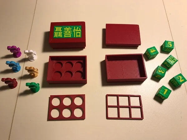
But not just any box! It's a modularized box! Or rather, the OpenSCAD code to generate the box is modularized. The point: efficiency of flexibility. The OpenSCAD script results in one command for each of the box parts: the bottom, the lid, the part-specific insert, and the name plate. You can produce many configurations of the box with hardly any time required, no cloning, re-modeling, etc.
Eric Hallberg, if you're reading this, feel free to borrow the technique for the automobile industry. Seriously, no charge. Happy to share. :)
The lid changes size simply by changing a variable. The dice fit in the box with the default lid size, so rendering the lid is as easy as typing boxlid(). The Film Tycoons pawns are taller, though, so boxlid(14); makes a taller lid to accommodate. Likewise, the nameplate is a separate piece which fits somewhat snugly (and even more so with a little epoxy) to the lid; I could have printed the name directly in the lid, but the separate plate allows for a lot more flexibility.
The round or square inserts -- similar approach. Specify the size of the holes in the insert and the code centers them appropriately. Most important here is that by printing the insert separately the box bottom can be printed ahead of time. (I didn't take the extra step of combining the round-hole and square hole inserts in a single code block, but I'll likely do that before blogging about the actual code.)

Odd "box" trivia: the Simon & Garfunkel song The Boxer is NOT about a dog after all!
Oh, and the length and width of the box? Also variable-driven. If I needed ten dice for that Super Secret Professional Double Yahtzee League, it's just a matter of tweaking two numbers and you suddenly have a ten-die box.
The only part of the project that can't be tweaked and re-printed in seconds* is the Chinese writing. That's a bigger challenge than putting text on the nameplate; the characters have to be brought into another program as a graphic, converted to a format OpenSCAD can understand and extrude as a 3D object, then incorporated into the model. Another topic for a later blog.
And Missy, I still feel slightly guilty about the alliteration/musical thing, but I'll try to make it up to you. Maybe with some 3D printing haiku or something. You're welcome in advance.
* That's not exactly true. Nothing 3D prints in "seconds." At least, not in so few seconds that it wouldn't be more appropriate to measure in minutes or hours. The more accurate way to say this would be, "...tweaked and started re-printing in seconds."
More Fun With Electricity!
I finally got around to a bit more guided testing of my conductive ABS plastic this week, thanks to some direction from /u/eb86 and /u/SaffellBot from Reddit. They suggested to simply measure the resistance of the conductive filament rather than the voltage drop. Eb86 also gave me more direction on measuring the voltage drop with the filaments in series and the multimeter in parallel -- haven't gotten to this yet, but I will soon.

If you haven't read my previous blogs on this subject I'll repeat the disclaimer that I'm a horrible dabbler with electronics. I've no issues with admitting my amateur status at anything (it's a pretty good approach for learning stuff, you know) and I love it if my dabbling inspires other people, but remember -- everyone's responsible for not burning down his or her own house.
This one's a pretty safe experiment. Same 3D printed conductive block that I described in this blog. This time I simply plugged the multimeter directly into the block to measure the resistance. The reading was a pretty steady 143k ohms. That's a heck of a lot more than the 330 ohm resistors that I normally use with my LEDs; I'm surprised the LED lights up at all with the conductive filament in the circuit.
Simple result: while this arrangement does conduct electricity, the resistance is pretty high. (Sounds like I could be describing a marriage at times, huh?)

Appropriate music suggestion: Muse, "The Resistance."
Yesterday's experiment also resulted in a mystery*. When my 3D printed block is in the circuit without a resistor the LED doesn't light at all. Logic suggests that the resistor and block together would increase the resistance, but no one ever said that logic is key to science, right?
The logical next step (to me) is to print some different configurations of the conductive filament and figure out which offers the least resistance. I've already got this latest one at 90% infill, is the resistance higher or lower with more dense infill? Is the diameter of "wire" a contributing factor? Like a circuit board, perhaps a very thin layer of conductive plastic is better than the wire I have now -- say, .1mm or .2mm as opposed to ten times larger.
More to come...but after I've finished more of my actual work for Film Tycoons.
*By "mystery" I mean, "I don't know the answer to this, though it's very likely that someone with more knowledge of this subject probably sees my mystery as a basic fundamental concept. You can laugh, but you know who you're coming to when you're trying to figure out a SQL database, don't you?
Oh, Amazon Prime, How You Spoil Me
Last December I thought it'd be fun to 3D print replacement tiles for my Settlers of Catan game. The Catan board is made by placing hexagonal tiles next to each other; each tile represents one lot of resource-rich land (either wood, wheat, wool, brick, or ore) and the set is surrounded by sea tiles, which may have harbors for trading. The junctures where three tiles come together provide spaces for villages and cities to be built, and the borders between tiles are roadways.
I chose this tile set from Thingiverse for one feature -- small holes along the underside of each tile allow magnets to be placed inside. The magnets are just strong enough to keep the tiles together during incidental bumping throughout the game. (Otherwise the game could be retitled Settlers of San Andreas.)
The preferred magnets are pretty specific: 3mm diameter spheres. Go ahead. Search for "spherical magnet" on Amazon. You'll find that the world's biggest retail clearinghouse comes up pretty dry. But no fear, the Thingiverse designer provided a link to a company in China which sells these. The company is called TinyDeal, and back on December 16th I ordered myself a few boxes.

"It seems to run on some sort of electricity!"
Fast forward -- no, wait. Crawl forward to February 1st and my magnets arrived.
Sure, the magnets came from China. The customer's expectations should be set appropriately; it takes a long time to ship goods from China. Problem is, some behemoth has been steadily resetting the general expectations of the American consumer in regard to shipping time. With Amazon Prime we regularly receive goods in two days, one day, or even the same day that we ordered them. During the Super Bowl they even advertised the possibility of receiving your Doritos via drone in minutes, right? If my craving for simulated nacho cheeze flavoring can be quenched in an hour, surely my need for tiny magnetic parts can be accommodated in less than six weeks.
The business lesson is pretty obvious -- scarcity is the only compelling factor to order from TinyDeal. And even that could be alleviated easily by someone who orders in quantity, stores in the U.S., and is able to fulfill my magnetic need for just a few dollars more, but within days. That's worth paying for, right? I'm going to refer to this theoretical concept as importing. Maybe I'll see it during my lifetime, though I'm pessimistic. I'm still waiting on my flying car.
I Have No Job, But I Have A 3D Printer
(I thought that was a bit catchier title than, "Conductive Filament Part 2." At least it gets fewer conflicting hits on Google, right?)
I meant to post this earlier in the week but as the title subtly hints, I was laid off on Monday. That took a bit of wind out of my blogging sails this week. Ironic, given that I've abruptly had time on my hands. On the plus side, I'm interspersing my job search time with 3D tinkering and helping get the new 3D printers set up at my daughter's school, so...let's do some more filament testing.
In Part 1 of this subject I started testing the actual conductivity of STAR Alchement's Conductive ABS Filament. In technical terms, the results were middlin'. While my printed coupler did conduct electricity, it dropped the 8V output from my battery to just over 4V. I decided to change a few things on the next attempt.

I was out of bananas, so I used a penny for scale.
The coupler in this experiment is regular ABS (Hatchbox Gold, not to be confused with the awesome double album, ABBA Gold) while the inside is Alchement's Conductive. The sockets are the same size cones described in the first blog; the wires pressure fit snugly into the ends of the block. Each cone tapers down to a 2mm diameter cylinder, and the entire arrangement is 40mm long.
One other key change -- I separated the processes and used different infill densities. The gold box is 25% infill, same thing I use for most prints. The conductive part, however, is at 90% infill.
Similar test to before. Measure the battery output alone, then add the coupler to the circuit and measure again. No need for a "before" shot this time, it's pretty much the same as the first time. (It's the same battery, same battery clip, and I promise I haven't been running my Walkman off it in the intervening week.)
You can see the results below. Although the voltage still isn't at the full 8V the battery was putting out before, it's much higher at 6.26 than the 4V from the first piece that I printed. It was also quite steady. Once the wires were seated firmly the reading hardly budged. The obvious conclusion is that the 90% infill made the major difference.
Next steps will be trying a few more variations of the "wire." The connecting wire here is 2mm diameter over 20mm (each of the sockets is 10mm deep) and perhaps that volume causes more diffusion. (Mike Patterson, if you're reading this, stop laughing. My line is business intelligence, not electrical engineering.) After a visit to PAX South this weekend I'm going to print more models with 1mm or .5mm wires and see if I get any noticeably different results.

First Test of the Conductive 3D Filament
One of my favorite things about 3D printing as a hobby is that new capabilities are developing almost daily. It seems like a new type of filament is on the market every day, or someone has assembled a new extruder to do anything from create edible cake decorations to pouring concrete housing. A while ago I ordered [STAR] Alchement's Conductive ABS filament and this week I started testing it out. The significance of this as a printing capability is pretty obvious. If you've also got an interest in electronics, it's possible to simply print some circuitry as opposed to leaving cavities for electronic parts in your prints. My dual extruder printer should be particularly well suited for this -- print regular ABS from one extruder for the main print, and conductive from the other to make "wires" through the print.
Of course, this all depends on whether or not the conductive filament is truly conductive.
The Amazon reviews aren't promising. To date there's one question asked: is the filament truly conductive? One person has answered, and he rather vehemently says no, it's not conductive at all. Likewise, the sole review gave the filament three stars and claims that it's not conductive "by any means."

Well, I've got a roll and I like Alchement's other filaments, so let's give it a try. Here's my disclaimer: I've only run one test so far. I'm going to modify some of the prints to see if I can improve the results. I wouldn't claim that this first bit of data is conclusive.
For a simple conductivity test I printed a little connector, pictured to the right. It's just a rectangle of filament, 40mm long, 2mm sides. The final 10mm at each end is a hollowed out cone, 1mm wide at the very end, narrowing down to .4mm. Hence, a jumper wire or the leg of an LED or resistor pressure fits into the socket and there are 20mm of "solid" filament between the two sockets. (Quotes around "solid" because I printed this at 50% infill. One of the next things I'll toy with is printing the "wire" at 100% infill.)
Quick printing specs: because I'm dealing with a pretty small part and want the sockets to work well I changed my primary layer height to .1mm. The bed is set at 105C and the extruder at 230C. It printed quite nicely at these settings and given how small the part is, it took about 10 minutes.)
Time for some measurements. The picture on the left is the multimeter hooked up directly to the 9V battery. Not surprising, I'm getting just under 8V. (It's a veteran battery.) On the right, I've gone from the battery to my filament connector, then a jumper wire to the multimeter probe. Noticeable drop in voltage, down to 4V, but it IS conductive.


Some immediate thoughts: it's possible that my socket design isn't the best. The wires are all plugged in pretty tight; they won't fall out of the sockets without a good tug. It's worth looking at, though. Also, the aforementioned infill of the wire. In the current configuration (no pun intended) my "wire" is 4 square mm with 50% infill. When printing this as a wire inside another model I plan on making the wire a 1mm cylinder at 90% or 100% infill.
Of course, the multimeter is good for testing but not really a fun application. Here's a little more visual evidence of the difference, using an LED to demonstrate. Again, straight hookup on the left, conductive filament socket in the mix on the right.


Early conclusion: hell yeah, it's conducting electricity! No disappointment here, it's time for more experimentation. :)
Dialing In My Frustrating Frustum
Yesterday I decided it would be fun to create a 3D model of a pyramidal frustum. I have no idea how this popped into my head, but I've decided to blame it on my friend Mike P., from way back in junior high and high school. Mike had a great knowledge of the esoteric and was quite a good artist. It's quite possible that while we were playing Car Wars one day he made an offhand comment like, "If I designed a house it would be a pyramidal frustum." That'd be just like Mike.
So yesterday I decided to model my own pyramidal frustum, and because no project can be left simple, I decided to embed Fibonacci spirals in the faces. (Plus, anything with a Fibonacci spiral is automatically +5 in Mysterious, right?) You can see the OpenSCAD code for the modeling if you like, but here I'm going to talk about dialing in the FlashForge Dreamer settings to make a nice print.

The four prints in the photo are ordered left to right from first printed to final print. The first print's pretty bad. The copper layers are really uneven and the edges are stringy. The blue spirals look terrible -- the second extruder leaked blue filament everywhere, yet somehow managed to not fill well in the print itself. Go figure. I'm using Simplify3D to slice and in that first print, the Hatchbox bronze PLA was set at 180 while the Metalink blue was set to 200.
(My Dreamer has upgraded nozzles which tend to make Hatchbox PLA print at lower temps than the original nozzles. However, I just got this Metalink filament recently and used it to print all the sea tiles for a Settlers of Catan set quite nicely at 200C.)
For the second attempt I decided to turn on retraction and coast at end. I was trying to avoid using a priming pillar because pillars really add to the length of a print. I find that the priming pillar needs to be 10 or 12 mm square, minimum, to NOT break away from the print bed. When your pyramid is 30mm square at the base, that priming pillar adds significantly to the overall print time. So, retraction on to 2mm, coast at end of Simplify3D's default .2mm. Result: a still very crappy looking frustum.
Third attempt: increased the retraction to 5mm and the coast at end to 2mm. (Yeah, that's a big jump in the coast value.) I also lowered the temp on my Metalink filament to 190, since it was still leaking little drops of blue all over the place. The threading seems to have gotten even worse in this one.
Fourth try: all right, I'm turning on the ooze shield. I use this feature a lot when I print dice, since it helps prevent cross-contamination of the filaments. I'd been trying to avoid this since it adds to the print time; not quite as badly as the prime pillar, but noticeably. In this case, the print time went from 36 minutes to almost exactly an hour. Yikes.
On the other hand, the ooze shield made that fourth frustum come out far nicer than any of the previous attempts. I did leave my retraction and coast set the same as the third attempt, but the ooze shield clearly made the biggest difference. I'll have to experiment further with tweaking the retraction, extra restart distance, and other related settings. For now though, when someone has a critical need for a pyramidal frustum, I'll have to stick with the ooze shield.
Modular Printing to Avoid Support
I decided to model some custom pawns for Film Tycoons this weekend. The "old fashioned" film camera might be the most iconic (non-copyrighted) symbol of American film, so it's the most obvious pawn choice. It also has a very pleasing silhouette; you glance at it and know immediately what it is. That outline structure causes some 3D printing issues, though -- there are a lot of unsupported overhangs at angles which can't be printed.
Quick lesson for those who aren't familiar with 3D printing: an unsupported section is any bit of plastic which does not have plastic directly beneath it. Consumer grade 3D printers work by laying down layer after layer of plastic. (The layers in these pawns are .2mm tall.) The layers can gradually shift as the print builds; up to a 45 degree incline is quite safe and you can get even steeper if you print slowly. Hence, the tripod legs will print with no problem.
Check out the front of the lens housing, though. That's 90 degrees to the print bed and hanging in thin air, about a centimeter above the table. Try to print that and you're going to end up with a big glob of plastic

One way to handle this is by printing support. The slicer (the software which translates a 3D model file to code for the 3D printer) can add in columns of plastic with a more diffuse density and a weak connection to the layer being supported. The support columns break off easily from the part. However, supports increase the overall print time, they can leave rough spots on the surface of your model, and they can increase risk -- if the support doesn't have a wide base it can break away from the print bed and cause your print to fail just as easily as the finished part itself.
Instead of printing one solid part with support I decided to cut my model into three pieces, each of which could be printed with no support, then glue them together. From the base to the connecting point on the tripod was one logical piece, the camera body and lens are another, then the reels.
I hate gluing flat pieces together, though. No one wants to hold two pieces together for ten minutes while the glue dries, right? Especially if there are two gluing operations per pawn and I'm printing six pawns. That's...a lot of time that I could be playing Ruzzle.
The answer: pegs and holes. (Ikea figured this out a long time ago, too.) The camera housing has a hole on both top and bottom. the tripod and reels each have a peg. Besides making the gluing easier, this helps ensure that the pieces are aligned the correct way.


I actually turned this 90 degrees to the left for printing, so that the lens pointed straight up.
I also use this little technique when slicing larger prints into pieces that will fit on the printer. My Maltese Falcon is an example of that; I wanted it to be the same size as the movie prop, which meant slicing it into three parts. Peg holes helped keep his parts flush at reassembly. (Clarification: I didn't create this awesome Falcon model; I printed someone else's model from Thingiverse.)
A couple of other interesting production notes. First, the to make the peg/hole arrangement really work well, the holes should be cylinders with different diameters at the ends. In this example my pegs have a diameter of 4.5mm. The holes have a diameter of 5mm at the opening and 4.6mm at the back, providing a snug pressure fit. The pieces actually stay together pretty well without any glue.
Second, note the orientation of the housing -- I printed it with the back side flat against the print bed, lens pointing up in the air. Why? The peg holes have a 90 degree overhangs. The one on the bottom could potentially sag during the print. Probably not a big worry in this case because the widest of those "roofs" is only 4.6mm, but it's still a good practice.
Sometime soon I'll post the OpenSCAD file for this model either here in my site or on Thingiverse.
Organized Resistance
One of the guys at the Fort Worth Library Panther Lab Maker Space recently showed off a very cool method of storing the resistors in his electronics supplies. He uses a sewing kit with an array of small, individual boxes which close securely, one box for each size resistor(For the uninitiated, those plastic boxes with "configurable" compartments are terrible for electronic parts. The walls are never flush to the bottom of the box, so whenever you pick it up stuff slides beneath walls and gets all mixed up.)
I scoured the sewing stores nearby but couldn't find the same organizer. Merry picked up some clearance fabric, but that wasn't really in the success criteria for the mission. I did find those storage systems on Amazon but they were over $50. I didn't want to pay that and wait two days for shipping when I could design my own solution and, well, wait two days for it to print.

I had these plastic test tubes (okay, they're pin holders, but "test tube" sounds more technical) and decided to build a rack that could organize them. First step was a single rack, modeled in OpenSCAD. Couple of key criteria: first, the seat at the bottom and the collar slightly above needed to hold the tube in place when turned vertically, yet the collar has to be low enough that the tube can tilt and be extracted even when there's a row above. Second, I needed enough space for my fat fingers to get hold of these things. And third, I want to be able to connect any number of holders to accommodate whatever size box I find for them.
I did make a 5-holder version once I was happy with the single. It's pretty easy in OpenSCAD; there's a module for a single holder. Call that module five times with a few translate tatements and you're good to go.

The connector holes are 2mm diameter, so the knobs on the connector straps are slightly smaller -- 9.25mm at the base and 9mm at the tip. (The width of the strap is also a pressure fit, since the recess is 10mm wide and the strap itself is 10mm wide. Yeah, probably should have made the strap just a tad more narrow, but hey -- it pressure fits.)
Next step, of course, is to find or print a box to carry these in, or perhaps print something to mount them on the wall in the electronics lab/office/game room.
Here's the Thingiverse link for anyone interested in printing their own.
It's Not The Heat...
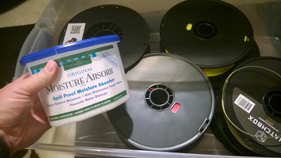
I used to keep eight or ten of my 3D printer filament reels on the pipe framework I built around the table, partly because it's convenient to have them handy there and partly because I think it looks cool. However, this summer I read a number of pretty convincing arguments regarding how quickly filament can suck trace moisture out of the air. This can cause problems with inconsistent filament feed while printing, so I decided to try a different storage route.

Underneath the table I know have some large plastic bins -- each one cost about $6 and can hold ten spools. That leaves just enough room for one of those nifty water absorption thingies; they cost a couple of bucks each, you put them in a humid area such as a laundry room or North Carolina, and they draw the moisture out of the air via these magical pellets that you shouldn't eat.
I really didn't expect to have a whole lot of moisture in a plastic box in my office, so I was pretty surprised when I checked one of the absorption things after four months. Shook the container and heard the slosh slosh slosh -- more water than pellets in there. Go figure. If that much humidity was available inside the bin, apparently my totally exposed filament reels have been sucking up a lot of water previously.
As long as I'm posting pictures of the table, I'll point out that it was the first major improvement made to my printer. Yeah, everyone else likes to replace the motors and bearings with some super-high efficiency versions they stole from ARGUS or swap out the nozzles for premium heads they made by melting down Wolverine's bones, but the table is without a doubt the best upgrade I've made. When I first bought the printer I had it sitting on a card table and the entire table would sway during printing. Building a solid table with 4x4's for legs took care of that, plus provided a platform for those 1/2" pipes to hold the reels. But now that I've decided to keep the filament dry, I'll have to find something else worthwhile for the scaffolding.
The Most Useful Thing...
There are quite a few standard questions you get asked when people find out you do 3D printing. The most frequent is probably "Could you 3D print a gun?" (The answer is yes, of course you can, but the follow up is no, I have no interest in doing so.) I think the second most common is, "Did you see the video about that guy who built the massive 3D printer and made a cement castle for his daughters?" Yes. I did see that video. That guy's cool. And he built his own ginormous 3D printer which extrudes cement. I successfully assembled a daybed from IKEA on the first try, so I'd say we're even.
One of the most insightful questions I get asked is, "What's the most useful thing you'd 3D printed?" That's a good question. It's really fun printing models of D&D creatures, jungle gyms for my praying mantises, or a new emblem for the front of my Canyonero, but useful -- that's getting into territory which makes the printer more than a toy.

I can think of a few truly useful things I've printed. The E*nable hands come to mind, of course. For someone without a hand, a 3D printed hand is pretty, well, handy. Lego Minecraft daylight sensors and redstone lanterns. They're mostly décor, but do serve a purpose and were good practice for more complex electronics projects. Business card boxes, playing card boxes, and special occasion heart boxes, all very practical.
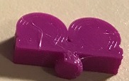
But here's the object that gets everyday use. Every single day. Almost 24/7, as a matter of fact: the glow in the dark robe hook.
It's one of the very first things I modeled myself. If you're thinking that the rudimentary shape was a product of being new to 3D modeling and that I've gotten better over time, you're half right. I'm no better at elegant visual design now than I was four years ago, nor thirty years ago, for that matter. Apparently graphic art is not a skill that just develops naturally with age. But that's ok, because this hook has function. Two functions, in fact. It holds my bathrobe conveniently close to my bed, and it glows in the dark. Enough of the hook shows that I can find my robe in the middle of the night, and I can easily hang it back up again without turning on a lamp.
And there you have it. I've capitalized on decades of electronic development by producing a hook upon which I can hang my clothing and locate it in the dark. You're welcome, Technology.
Dragon Wings: Printing with PLA and PVA
Fun note: I've been reading Ready Player One and updating my Minecraft web page, so I've had to correct "PVP" into "PVA" about five times in this blog…
Though PVA filament offers some great opportunities to manage some 3D printing situations, I just don't see a lot of discussion about it. I'm guessing that's because to really get the most use out of PVA you need to have a dual extruder printer. I don't know what the numbers actually are on single versus dual, but my gut feel is that only about 10% to 15% of us 3D printing hobbyists have duals.
Personally, I think PVA and other "utility" filaments are an excellent motivation for having a dual extruder printer, not to mention the obvious plus of being able to print two colors of PLA or ABS at the same time.
PVA filament has two very useful properties. First, it bonds with PLA as if it actually is PLA itself. Second, it's water soluble.
Last year I wanted to print this beautiful copper dragon model that someone had introduced on Reddit. The model was already in pieces rather than a single print, and each wing was a separate piece. The challenge I ran into immediately was that it was hard to orient the wings in such a way that I could get a nice, smooth print. The ideal method would be to orient them vertically, but this was an extremely tenuous way to print. No flat base to adhere to the print bed. Adding even the lightest support made the wings look terrible once the support was removed, and I never think that sanding and filing looks as good as just getting a good print in the first place.
So, I decided to try the PVA method. Using OpenSCAD I created a very simple block of plastic around the wing. Exported that block as one model and the wing as a second. In Simplify3D I told the Dreamer to print the block in PVA and the wing with a nice copper PVA.
As you can see in the pic, I really overdid it on the amount of PVA -- I could have made that block significant smaller and still gotten the same support I needed, but…live, learn, refine. Didn't matter. Once the print was done I dropped it in a bowl of water, and within two hours that block of PVA was gone and I was left with a very nicely printed dragon wing.
One other hindsight note, along with a warning. I should have divided the print into two processes with one stopping at the max height of the PVA. The second process would have finished the wing and allowed the PVA extruder to cool back down to room temp. That top half of the wing took about an hour to print, and because I only used one process, I had non-moving PVA filament cooking in a 185C extruder. Not good, and probably led to the demise of that nozzle about two months later.

Copper dragon with banana for scale.

Minimal support...fail!

Wing embedded in PLA block.
(For the uninitiated, another characteristic of PVA is that it is NOT a "heat it up to 240C to solve all problems" type of filament. If you heat it beyond 200C it actually solidifies and will destroy your nozzle. Read up carefully on how to use PVA correctly before you try it.)
Other applications? How about creating a single-print hinge, where the empty space between the pin and barrel are initially printed in PVA and rinsed out? There are other specialty filaments to consider, too, such as NinjaFlex. Though I haven't tried it yet, I've considered using NinjaFlex in one extruder and PLA in another to create a flexible joint between two objects without having to print separate pieces and snap them together. Also, there are no electrically conductive PLA filaments available. They've still got plenty of room for improvement, but imagine the possibilities of printing your own circuit boards with regular PLA in one extruder and conductive in the other. Arduino/Raspberry Pi hobbyists, eat your heart out.
And, of course, there's always the standby of multi-color printing. After all, who doesn't like their name on everything they make?
Dual Extruder Dice
Quick example (and test blog) demonstrating one of my favorite things about my FlashForge Dreamer: dual extrusion.
A dual extrusion printer, as you've probably guessed, has two extruders. This means you can run two filaments through the same print without having to pause the print and change the filament. Consider these dice -- since the printer lays down plastic in .2mm layers, if I wanted to print the dice with a single extruder printer I'd have to pause on almost every single layer, change the filament, and resume printing.

Personalized dice for a Reddit Gifts match.
Keep in mind that a filament change means moving the extruder head away from the print, heating it up to 240 C, feeding the new filament while flushing the own, then lowering the temperature back to ~180 C before resuming the print. That's a lot of time, a lot of unnecessary heating and cooling of the extruder nozzles, and a lot of wasted filament.
That's 75 filament changes. Yikes. There are a couple of ways you can minimize that pain or get around it. First, if you had a bunch of dice to print you could produce ten or twenty at once; that would get you more print time for every filament swap. (But still, 75 filament changes!) You could also leave the pips or numbers as voids, either painting them in after printing or using a 3D pen to fill in the blanks.
I do enough multi-filament printing that I'd much rather just have the dual extruder printer, of course. And, as I'll show in a future blog, the dual extruder also provides solutions for some tricky printing scenarios.